Part 2: How the TV Antenna Was Made
EXTRA: At the page bottom learn how make this antenna without test equipment!
Antenna Layout
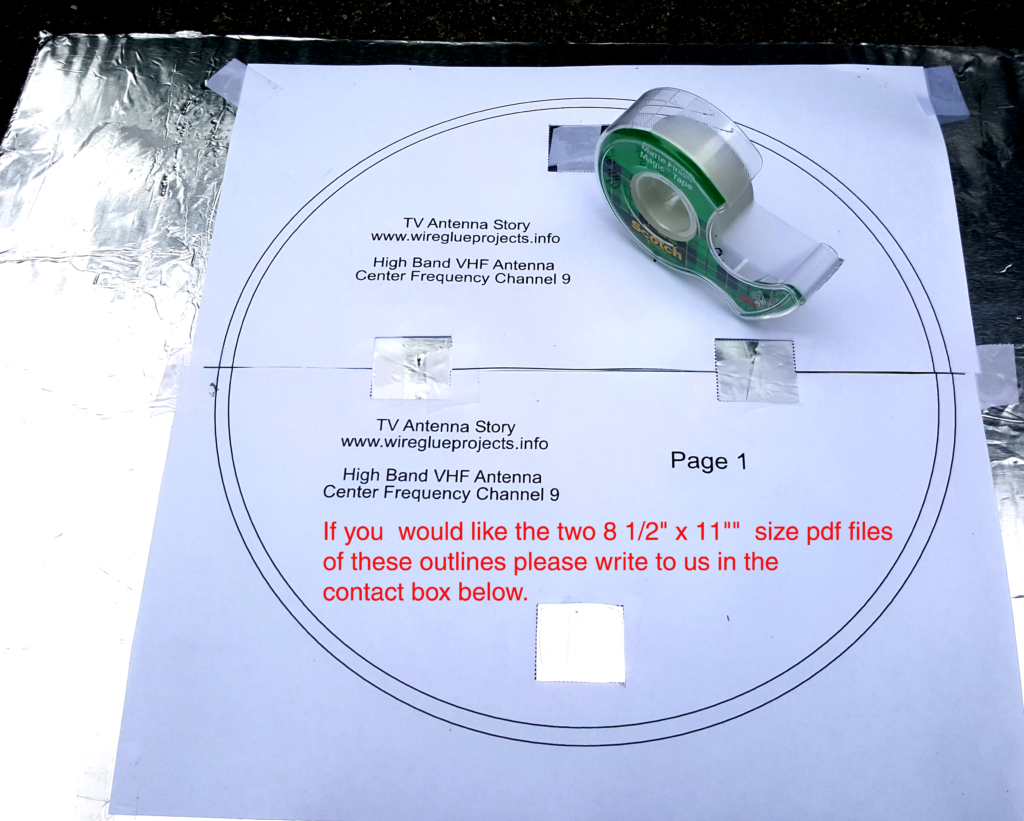
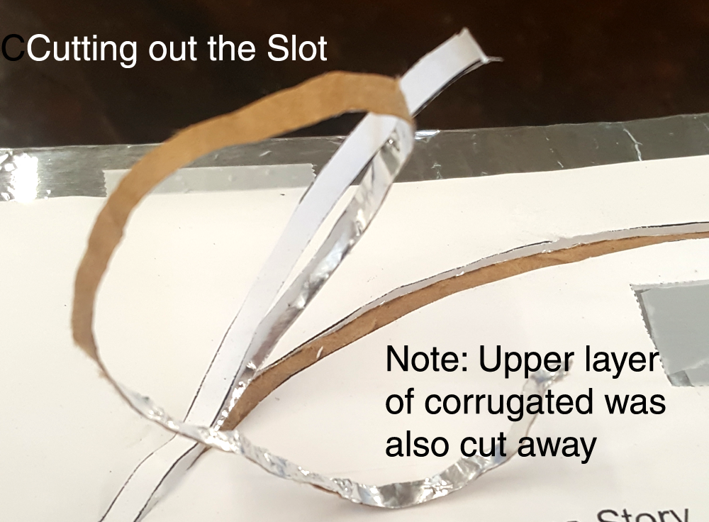
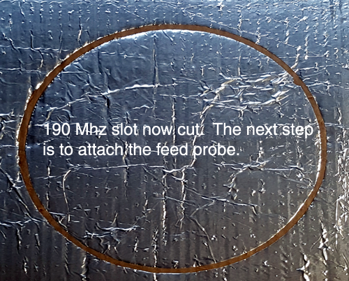
Matt and Penny got to work building the deep-fringe antenna. First, 4 pieces of 5 millimeter plywood were cut to 14 x 14 inch square sheets and scrap corrugated glued to the top. Then heavy duty aluminum foil was glued to the top of each sheet. Next, Penny laid out a paper pattern of the slot antenna on 2 pieces of 8-1/2” x 11” paper, attached them to the aluminum foil and cut out the slot with an exacto knife. Matt said to Penny, “Be sure to take off the top layer of the corrugated when you cut as the white glue readily absorbs RF and will eat up our signal.”
Wiring up the Antenna
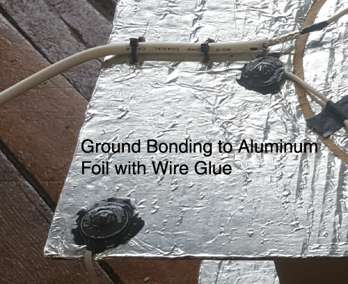
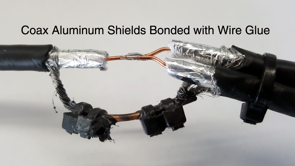
The feed probes were fashioned out of 12 inch lengths of solid 12-gauge copper wire. They were bent into a horseshoe shape with the center conductor of the coax soldered to one end and the other end bolted down to the aluminum foil with a screw and a washer which also connected the coaxial cable shield. Finally, Anders Products Wire Glue was applied to this connection to bond the aluminum foil to the copper wiring.
Half-inch diameter threaded rods were used to bolt the upper and lower boards together so they were positioned to 12-1/2 inches apart. These bolt connections were also overcoated with Anders Wire Glue to provide an electrical bond between the aluminum foil and threaded rods.
Matt asked Penny, “Do you know why we are electrically connecting the upper and lower boards, I mean the director and reflector together?” “Well, I figure”, Penny said “This is to get the antenna to work but is there more to it?” Matt said “Turns out there is.” Because not only does the reflector act to increase the antenna’s gain it is also acts as an electrical shield to reduce noise from nearby computers and such. Penny said, “I see the advantage as the computer inside the TV probably emits plenty of noise.”
Testing
Matt added, “Although not related to our antenna, do you know what the digital data rate is for HD television? Penny said, “I have no clue.” Matt said, “It turns out to be 19.2 million bits per second or MBPS, which back in the 1970s, when the HDTV standard was invented, was a really fast. But when you think that your 4-G cell phone operates at 72 MBPS, by today’s standards, HDTV is really slow.” Penny smiled and said, “Who would’ve thought?”
Penny said to Matt, “One of the things I like best about working for you is that no question is too stupid. I have two of them in regard to HDTV antennas: First, I understood that HDTV was all up on UHF band yet WMUR is transmitting their HDTV on the VHF high-band. How come? Second, why is the polarization circular?”
Matt said, “You are right that HDTV started out on UHF but the TV stations found that it took about five times more transmitting power to get the same coverage as they used to have on their original VHF channel. So most stations asked the FCC and got permission to use their old VHF frequency for the new HDTV standard, saving them both transmitter wear and tear along with their power bill. As to your question about circular polarization, the change from horizontal to circular came about in the 1970s when it was discovered that circular polarization provided a stronger signal in densely crowded cities.” Penny said, “Wow, so interesting: Things I never knew.”
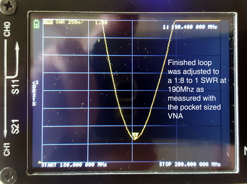
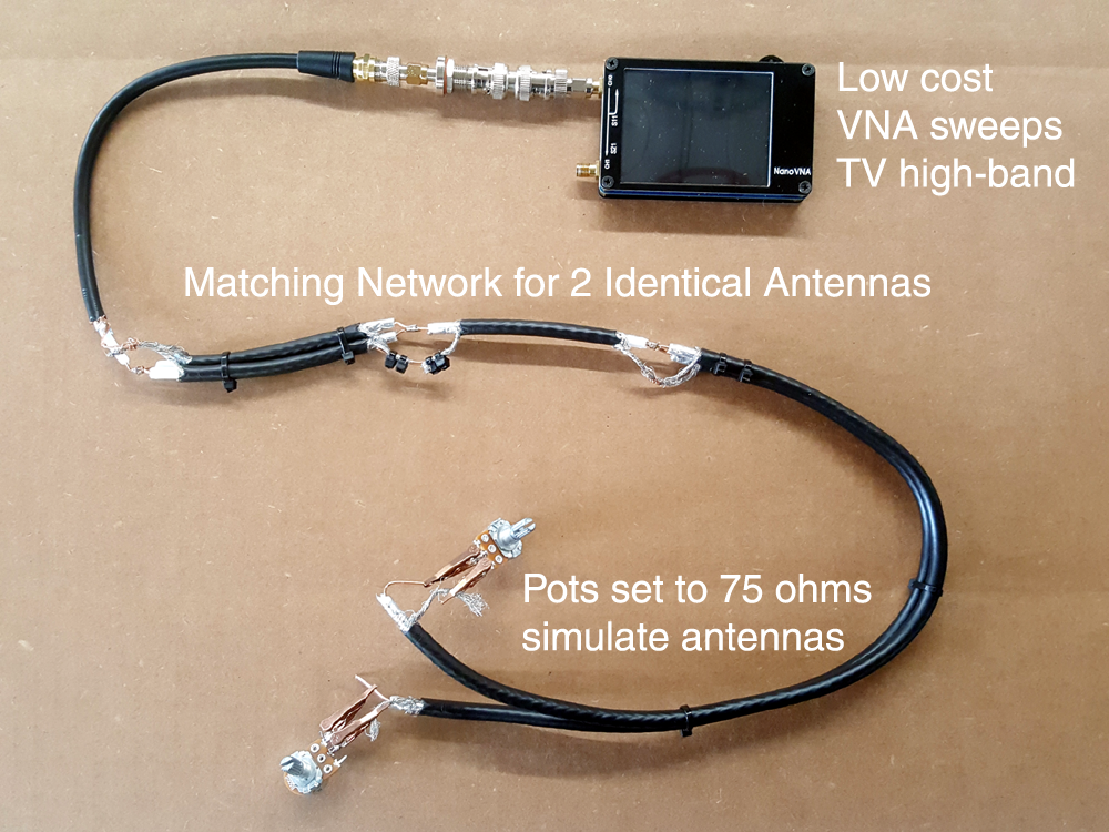
Reaching into the test equipment drawer, Matt pulled out a $60 pocket-sized Vector Network Analyzer (VNA) and gently placed it on the bench in front of Penny. He went on to say, “You are going to need this tool in order to figure out what is going on inside our antennas and the matching network which will be used to get these antennas to work together as a team.” Penny said, “I remember when you taught me how to use this device a while back and it is truly an amazing piece of test equipment. But I see a problem: We are designing for a 75 ohm system and this VNA is intended for 50 ohm measurements. How do we overcome this issue?” Good point Matt said and there is a simple answer which is a 75 ohm load will provide a 1.5:1 SWR mismatch so we will build this into our measurements. To show you what this will look like on the VNA screen and to explain another part of our test strategy, go over parts collection and find two, 500 ohm, half-watt potentiometers (pots).” Penny got the parts and soldered a pair of alligator clips to each pot, one to the center wiper and other to one of the remaining terminals. Mat said, “Now let me show you how these can become non-inductive terminating resistors.” “Really, Penny said? Up at these high VHF frequencies I think the resistive element of this pot will look like a hair-pin loop inductor to the VNA.” Matt said, “Well, not really as we are only using a small 75 ohm segment of the 500 ohm resistive element inside the pot so what we end up with is a variable non-inductive resistor. To prove this to you, first set the pot to 50 ohms scan it with the VNA over the VHF high-band TV range which is 174 to 212 MHz. You will note the 1:1 SWR and then set the pot to 75 ohms and try again.” Penny did the scan and much to her amazement she got back a 1:1 SWR at 50 ohms and 1.5:1 at 75.
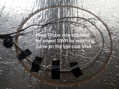
“ OK, Penny said I think I can now adjust the feed probe for resonance at 190 MHz and these pots will serve as the terminating resistors to evaluate the matching network you have been telling me we are gong to need.” While watching the SWR on the VNA screen, Penny started adjustments by taping down the ground side of the feed probe to the foil covered active element with aluminum duct tape. Once each antenna was close to the final resonance she then carefully bent the feed probe to get and exact match. With the antenna feed probes for both antennas tuned. Penny said to Matt, “Take a look at the Smith Chart for one of these antennas on the VNA. As you can see the match is nearly perfect with the capacitance of the coax showing up on the chart as well” (If the reader would like to learn how Matt taught Penny to use this pocket-sized VNA, drop a note into the message box and I’ll see if Matt would be willing recall the story).
Next, they tackled the problem of how to couple these antennas together for increased gain
Teaming-Up Two Antennas
With a curious a smile Penny asked Matt “Can it really be done, I mean connect two TV antennas in parallel like batteries to increase the signal power?” Matt responded, “Yes it can and it was figured out by the great pioneer of TV antenna design, John Winegard, around 1960.(1) In those days there was just one TV station in a city so he figured out how to stack multiple antennas on top of each other and then couple them together to provide an increased signal strength for folks far away. This fellow was such a brilliant inventor of TV antennas that there is a twice life sized bronze sculpture of him carrying a prototype antenna over his shoulder in front of the Winegard factory in Burlington, Iowa. Someday, if I ever get out there I would like to see this sculpture in person. Now here’s what he discovered: The two TV antennas must be exactly identical and the feed-lines from each antenna must be exactly the same in length such that the signal arrives from each antenna in exactly the same phase and amplitude.” “Back then TV antennas were fed with 300 ohm balanced lines known as twin-lead and the brilliance of the Wingard inventioon was that he as able to implement this impedance matching transfromer with just a pair of wires. Today’s feed system utilizes unbalanced coax so our impedance matching transformer design is bit more complex but the principles are exactly the same.
Matt said, “Penny, if you are ever down in Nashua, look at the TV antenna on top of the apartment building at the corner of Center and Palm streets. Up there you will see an old-time two-stack TV antenna still pointed south-east toward Boston.
While the lower array is mostly gone, still up there is the stack along with the WInegard matching transformer swinging in the breeze, its twin-leas feed connected to the center of the matching network: Just where is it supposed to be. I think he would get a kick that his matching invention is still up there some 75 years later.
The impedance of our antennas is 75 ohms and designed to feed unbalance coaxial line. So when these two signals are combined the result is effectively a 37 ohm impedance. Thus we’re going to need a highly efficient 2:1 step up transformer to bring the combined impedance of these two antennas back of 75 ohms with extremely low loss.“ “So that rules out the typical antenna splitter/combiners which use ferrite inductors?” asked Penny. Matt said, “Exactly, we need a really low-loss transformer designed for the VHF TV high-band.”
“And”, he went on to say, “I know just the transformer for our application which is both highly efficient and easy to make.” It was invented by the Swiss physicist Peter Bramham back in 1950’s and is known as the 12-wave transformer, although, it really should be called the 2-12th wave transformer.(3) “Now Penny,” Matt said “ There is a web calculator (4) to figure out the lengths of coaxial cable required to build this transformer and let me sketch out a drawing of what you need to build.
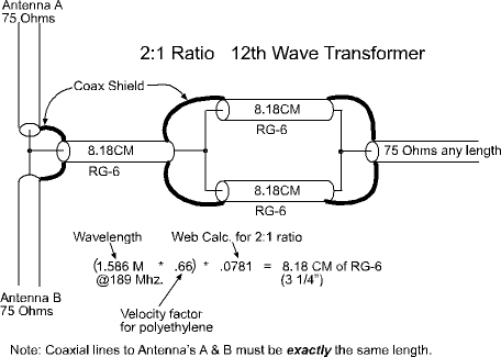
Penny Builds the Antenna Adding Network

Antenna is Ready
Finally, the two antennas and the matching network were mounted to a piece of wooden 2×4 and they were spaced one wavelength apart. A ¼-20 screw mount was provided in the center of the 2×4 beam to attach the antenna on an old camera tripod.
Road Trip
A short time later they threaded a string through one of the rafters in the repair bay and hauled the antenna into the air. With a big grin Matt exclaimed, “This test data looks just great!” But just then the next wave of freezing rain started to drum and crinkle on the steel roof of the building.
“Or not,” responded Penny grimly to the unwanted staccato noise. “But we have to do this Matt as after all, it is almost Christmas.”
Without answering the question, Matt said excitedly, “Grab that roll of RG-6/U coax, the tools and let’s go.”
The first part of the drive up north on Interstate 93 was OK as the road was well treated.
Staring out the windshield into the swirls of snow mixed with ice coming down, Penny’s mind turned to some really dark thoughts. Probably what triggered her into such a deep slump was when she learned of Amanda’s aunt’s troubles, and the way one more little trouble is just more fuel for the fire of the big one.
For Penny, Northern New England had been and she had hoped would forever be her home. But she knew under all this crushing student debt, her three part time jobs were just not enough. In particular, with very high costs of living up there she knew the only solution would be to move someplace where the cost of living is low and high paying jobs plentiful. North Carolina? Georgia? Some place South. Get full time work doing something and try to pay off that strangling debt.
This was not a new plan but an old plan with the intention to resign on January 1st. Now just nine days away, she was dreading every hour till that moment. She knew full well how Matt’s labor pool was disintegrating and how she from time to time was being sent out on jobs to fill in. Frankly, she liked the work and most of all she liked working for one of the smartest men she had ever known. No question this news would be devastating for Matt. But what else could she do?
Matt turned off Interstate 93 and started heading west on Route 25. The driving was getting really bad. The sound of the studded snow tires on the pavement for a few moments was followed by the hush as the truck rolled over packed snow and ice.
Despite the weight of the ¾ ton truck and the power of 4-wheel drive, Matt was struggling to keep the truck heading straight. He said, “To give me a break from this driving misery,” he said to Penny, “lets talk about anything to get my mind off this ice storm.” He went on to say, “So Amanda’s aunt likes the 11 O’clock news. Why? She thinks the weather man, Mike Haddad is cute? That’s a little more than I can understand.”
“Well”, Penny said, “They are her friends, and as we are all lost in the sea of COVID, I think that friends, no matter where you find them, are so important.”
“Got it”, said Matt. Their conversation drifted on as the roads became narrow and the storm more intense
Hope

Fortunately Penny knew how to find this place, as it was a tiny, single-wide trailer way out in the deep woods. The little trailer was perched up on a rise and as they approached the home they could smell a wood fire furiously burning. With a slight tap on the door they were invited into this little place by an older woman, and although a stranger to both of them, a truly welcoming person. Matt glanced at her clock and said “It’s getting close to 11 PM and we need to get to work.” “Oh, you’ve heard that story?” she blushed. “Yes and we’ve got a job to do,” Matt responded with a smile.
Matt dug out the antenna, now attached to an old camera tripod and a plastic tarp which served as its raydome. Penny ran the coax from the antenna up the front steps and over to the TV, hooked up the coax with crimped-on F-Connector.
“So you wanted to learn about the knife-edge stuff?” Matt said to Penny. He went on to say, “Let’s get on 55 direct, using our ham radio licenses, in order to keep the amateur radio 2 Meter national call frequency 146.52 MHz clear. I will watch the signal strength bars on the TV as you wander up and down in front of the trailer in order to find the best picture as you keep the antenna pointed to about where the peak of Plymouth mountain should be. Because we are picking up the knife edge diffracted signal off the peak, you will need to move about two wavelengths, or about 6 feet, to find the next signal peak. By that I mean, you will be doing your best ice dance!”
Back and forth she wandered with tripod in hand, while they chattered back and forth on 55 direct. Eventually she found the best hot-spot on a snow mound which in the summer would be a picnic table but was now buried deep below the snow.
Around this time the storm really started to blow hard and by the time Matt swung open the door and looked down the little rise to invite her back inside, Penny was covered with a gleaming coat of ice. For a moment, Matt paused and stared at her. She was a gorgeous sight with the beautiful face of a real ice queen.
By the time this was all set up the 11 O’clock news has come and gone. The last item up was the lottery drawing. Looking over Amanda’s aunt’s shoulder, Matt read the numbers off the screen and compared them to the ticket in her hand.
First three numbers were a match. Just luck, he said to himself.
The next three numbers were a match. Oh boy, Matt’s heart was starting to pound.
And the last three numbers: A match.
Matt was nothing short of stunned.
The next thing Matt heard was Amanda’s weeping aunt. She cried, “I did it!” “It’s paid for college. Now it’s possible!”
Yes, Matt said, very slowly, “You are now a multi-millionaire.”
But her gaze bypassed Matt and went directly to Penny; “Amanda tells me”, long pause, “that you are drowning in student debt?”
Penny nodded back.
“Well whatever it is, it is now paid by me. Done!”
“And, Merry Christmas!”
As the truck backed out of the drive and onto the country lane, out the windshield this time Penny was greeted with a new view. The storm has changed from ice over to snow and the dazzle of the headlights revealed a beautiful blanket of fresh white powder.
The beauty struck her and she started to mumble something to Matt.
“What’s that?,” he asked.
Penny said, “I just got the best Christmas present of all. Hope.”
++++++++++++++++++++++++++++++++++++++++++++++++++++++++++++++++++++++++++++
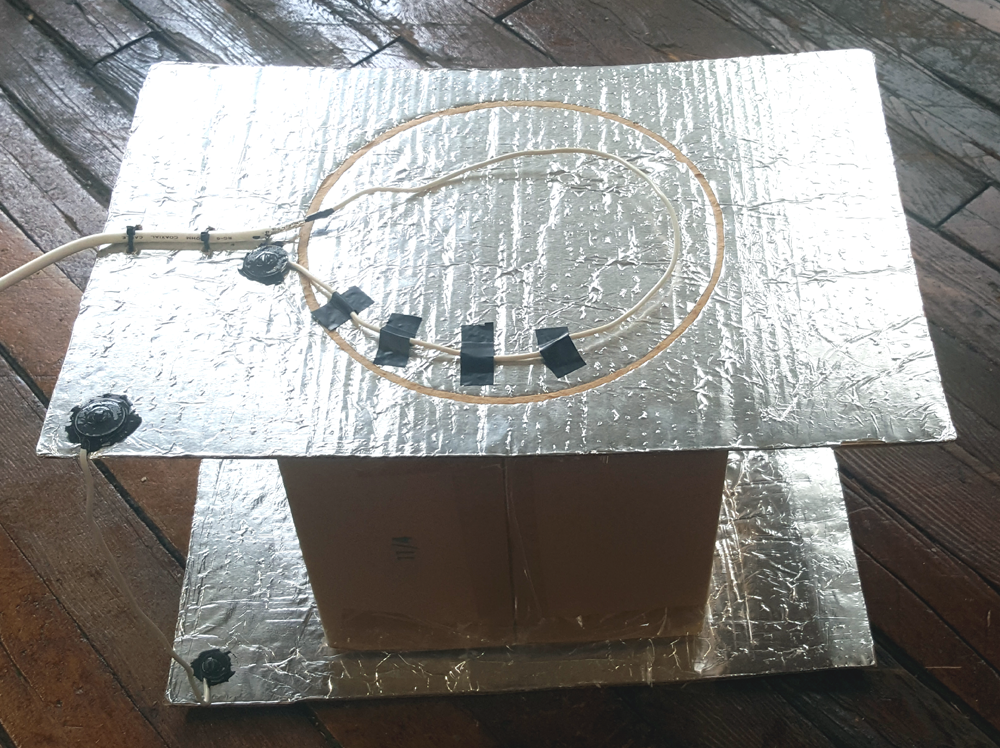
Epilog: As the next Christmas was approaching the dark clouds of an impending economic recession were starting form across the world. So Penny and Matt decided to build a batch of these antennas for indoor next-to-set placement and give them to needy families whom could no longer afford their cable bills. One of these antennas is shown in the top of this page and as Penny explained, “Built from a couple of discarded corrugated boxes and aluminum foil, it is amazing all the stations this antenna can pull in because of it’s powerful beam design combined with the advantage of circular polarization.” Matt added, “Since we didn’t need super-fringe performance, we just bent the feed probes to match the pictures on this page and did the final tune-up with the signal strength bars on the TV screen. No test equipment needed!”
For the their installations in Southern New Hampshire they would pick up 8 digital stations with the indoor antenna while the Boston area and along the South Shore 12 or more.
They both sincerely hope you will consider building a couple of these antennas and give them to needy homes as well. Possibly an elderly shut-in or a young family with growing children. They all need your help and kindness.
References
- Winegard deep fringe antenna Invention U.S. Patent 3,001,195
- https://www.microwavejournal.com/articles/print/68-how-i-developed-the-sixth-or-twelfth-wavelength-transformer
- http://leleivre.com/rf_bramham.html